
P24C Pressure Reducing and Flow Compensator
Datasheet
Download datasheet (PDF)Specifications are indicative. Final specification is confirmed at quotation.
Specifications
Confirmed at quote- Size Range
- DN50 to DN1000
- Pressure Class
- PN10, PN16, PN25, ANSI 125, ANSI 150
- End connection
- Flanged
- Operating temperature
- -10°C to 80°C
Standards
- Design & manufacture
- BS EN 1074-5
- Inspection & test
- ISO 5208, BS EN 12266-1
- Face to face
- BS EN 558-1
Configure your variant(manually adjust box on the right if you require a different spec)
- Size
- Pressure
- End connection
Materials
All available material options per part. Click a pill to set it in the configurator.
- Body
- Bonnet
- Seat
- Stem
- O-Ring
- Spring
- Bolts
- Bush
- Caulking Nut
- Diaphragm
- Disc Holder
- Fixing Holder
- Pilot
- Plug
- Screw
- Seals
- Seat Retainer
- Washer
Pressure-temperature rating
Maximum working pressure at each temperature, per pressure class.
| Class | Pressure | Min temp | Max temp |
|---|---|---|---|
| PN10 | 10 bar | -10°C | 80°C |
| PN16 | 16 bar | -10°C | 80°C |
| PN25 | 25 bar | -10°C | 80°C |
Dimensions per size(16 sizes)
| Size | L (mm) | H (mm) | PN10 OD (mm) | PN16 OD (mm) | PN25 OD (mm) | PN10 OK (mm) | PN16 OK (mm) | PN25 OK (mm) | PN10 N-Od (mm) | PN16 N-Od (mm) | PN25 N-Od (mm) | PN10 OB (mm) | PN16 OB (mm) | PN25 OB (mm) | Weight |
|---|---|---|---|---|---|---|---|---|---|---|---|---|---|---|---|
| DN50 | 230 | 177 | 165 | 165 | 165 | 125 | 125 | 125 | 4-Ø19 | 4-Ø19 | 4-Ø19 | 99 | 99 | 99 | — |
| DN65 | 290 | 202 | 185 | 185 | 185 | 145 | 145 | 145 | 4-Ø19 | 4-Ø19 | 8-Ø19 | 118 | 118 | 118 | — |
| DN80 | 310 | 219 | 200 | 200 | 200 | 160 | 160 | 160 | 8-Ø19 | 8-Ø19 | 8-Ø19 | 132 | 132 | 132 | — |
| DN100 | 350 | 243 | 220 | 220 | 235 | 180 | 180 | 190 | 8-Ø19 | 8-Ø19 | 8-Ø23 | 156 | 156 | 156 | — |
| DN125 | 400 | 243 | 250 | 250 | 270 | 210 | 210 | 220 | 8-Ø19 | 8-Ø19 | 8-Ø28 | 156 | 156 | 156 | — |
| DN150 | 480 | 333 | 285 | 285 | 300 | 240 | 240 | 250 | 8-Ø23 | 8-Ø23 | 8-Ø28 | 211 | 211 | 211 | — |
| DN200 | 600 | 428 | 340 | 340 | 360 | 295 | 295 | 310 | 8-Ø23 | 12-Ø23 | 12-Ø28 | 266 | 266 | 274 | — |
| DN250 | 730 | 478 | 405 | 405 | 425 | 350 | 355 | 370 | 12-Ø23 | 12-Ø28 | 12-Ø31 | 319 | 319 | 330 | — |
| DN300 | 850 | 538 | 460 | 460 | 485 | 400 | 410 | 430 | 12-Ø23 | 12-Ø28 | 16-Ø31 | 370 | 370 | 389 | — |
| DN350 | 980 | 550 | 520 | 520 | 555 | 460 | 470 | 490 | 16-Ø23 | 16-Ø28 | 16-Ø34 | 429 | 429 | 448 | — |
| DN400 | 1100 | 710 | 580 | 580 | 620 | 515 | 525 | 550 | 16-Ø28 | 16-Ø31 | 16-Ø37 | 480 | 480 | 503 | — |
| DN450 | 1200 | 720 | 640 | 640 | 670 | 565 | 585 | 600 | 20-Ø28 | 20-Ø31 | 20-Ø37 | 530 | 548 | 548 | — |
| DN500 | 1250 | 822 | 715 | 715 | 730 | 620 | 650 | 660 | 20-Ø28 | 20-Ø34 | 20-Ø37 | 582 | 609 | 609 | — |
| DN600 | 1450 | 885 | 840 | 840 | 845 | 725 | 770 | 770 | 20-Ø31 | 20-Ø37 | 20-Ø40 | 682 | 720 | 720 | — |
| DN700 | 1650 | 910 | 910 | 910 | 960 | 840 | 840 | 875 | 24-Ø31 | 24-Ø37 | 24-Ø43 | 682 | 720 | 720 | — |
| DN800 | 1850 | 1260 | 1025 | 1025 | 1085 | 950 | 950 | 990 | 24-Ø34 | 24-Ø40 | 24-Ø49 | 901 | 901 | 928 | — |
Technical drawings(3 pages)
Operating media
Typical applications
- Flow-compensated pressure reduction
- Leakage reduction
- District metered areas
- Smart water networks
Approvals
Features
- The P24C is a pressure reducing and flow compensator pilot that adjusts the downstream pressure set point in proportion to measured flow
- During high demand the set point rises to maintain adequate supply pressure; during low demand it falls to reduce background leakage
- Unlike time-based pilots, the P24C responds to actual network conditions in real time, giving the optimum balance between pressure and leakage at all times
- Top and seat ring guided stem and diaphragm assembly for long life and reliability
- All iron components are fusion epoxy bonded for corrosion resistance
- Easy maintenance without removal from the main line
- Nylon reinforced diaphragm for long-term service
- Drip-tight shut-off
- Globe design for superior control characteristics
- Ductile iron bodies for higher strength and durability
- Corrosion-resistant stainless steel seat and disc retainer ring
- Various pilots and accessories available for configuration into many different applications
- Special V-Port and double chamber are options, consult factory
- Meets BS EN 1074-5, ISO 5208, BS EN 12266-1 and BS EN 558-1
Description
The P24C is a pressure reducing and flow compensator pilot that adjusts the downstream pressure set point in proportion to measured flow. During high demand the set point rises to maintain adequate supply pressure; during low demand it falls to reduce background leakage. Unlike time-based pilots, the P24C responds to actual network conditions in real time, giving the optimum balance between pressure and leakage at all times.
Selection notes
This control valve is supplied for flanged installation.
Sizes run DN50 to DN1000, in PN10, PN16, PN25, ANSI 125, ANSI 150.
The body is EN-GJS-500-7.
Seat and trim options are AISI 304 and 316. The seat, not the body, usually sets the temperature and medium limit, so confirm it against the service before ordering.
Stated service media include water.
It is catalogued for Water & Wastewater.
Working temperature is -10°C to 80°C.
Built to BS EN 1074-5, BS EN 558-1, ISO 5208 and BS EN 12266-1.
Supplier remarks
- Head Loss Curve and Cavitation chart are stated in the source as curves, not tabulated points, so not reproduced here.
Available pressure classes
Pressure classes this product is rated to.
Used in
Related guides
Smart find
Searches our product catalogue using your spec. Drop a spec sheet or parts list (PDF, Excel, CSV, Word or text, several at once), paste a description or a part number and we'll find the closest matches for each. Anything we can't match goes to your RFQ as a custom enquiry for our team to source.Related Control Valves
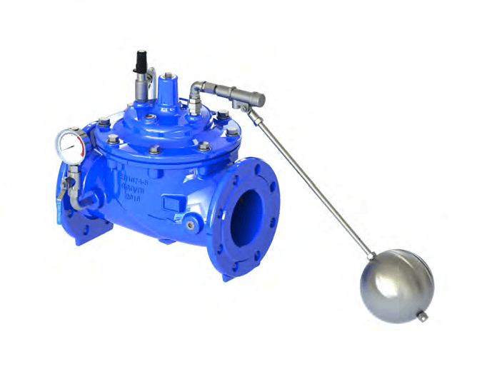 Control ValveREF 344
A100 Modulating Float Control Valve
- Type
- Control Valve
- Size
- DN50 to DN800
- Pressure
- PN10, PN16, PN25
- Body
- EN-GJS-500-7
- Standards
- EN 1074-5, BS EN 1074-5
Adds to your quote request, not a purchase. Refine size, pressure and material before submitting.
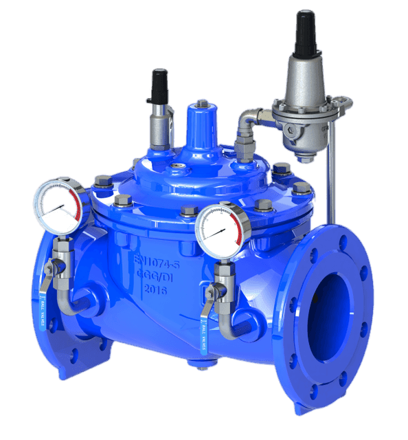 Control ValveREF 345
A200 Pressure Reducing Valve
- Type
- Control Valve
- Size
- DN50 to DN800
- Pressure
- PN10, PN16, PN25
- Body
- EN-GJS-500-7
- Standards
- EN 1074-5, BS EN 1074-5
Adds to your quote request, not a purchase. Refine size, pressure and material before submitting.
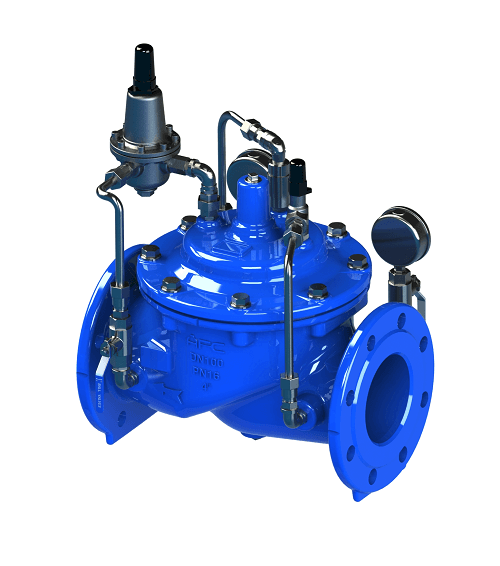 Control ValveREF 346
A203 Pressure Reducing with Check Valve
- Type
- Control Valve
- Size
- DN50 to DN800
- Pressure
- PN10, PN16, PN25
- Body
- EN-GJS-500-7
- Standards
- BS EN 1074-5, BS EN 558-1
Adds to your quote request, not a purchase. Refine size, pressure and material before submitting.
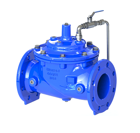 Control ValveREF 347
A300 Slow Control Check Valve
- Type
- Control Valve
- Size
- DN50 to DN800
- Pressure
- PN10, PN16, PN25
- Body
- EN-GJS-500-7
- Standards
- EN 1074-5, BS EN 1074-5
Adds to your quote request, not a purchase. Refine size, pressure and material before submitting.